
1. Installation
Search for "NSC Drone" on Google Play or AppStore, and download the app on your mobile device.For devices that don't support Google Play, you can directly download and install the APK file.
2. Access to NSC3 services
Accessing NSC3 services can be done by scanning a QR code, or logging in with an existing user. The access options can be found in the General Settings. In General Settings you can switch between On duty and Off duty modes.
3. Sending drone camera video stream to NSC3
In General Settings you can switch between On duty and Off duty -modes. When on duty, the drone camera video, along with other information such as location data, is automatically streamed to NSC3. When Off duty you can still operate the aircraft, but the drone camera video is not streamed to NSC3. You can see the current data transfer speed in the lower right corner of the Camera view.
4. Camera view
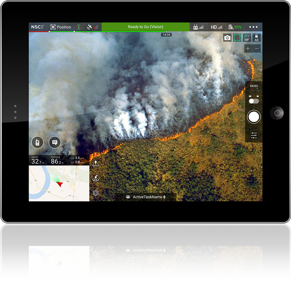
Android
iOS
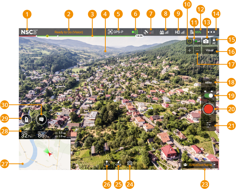
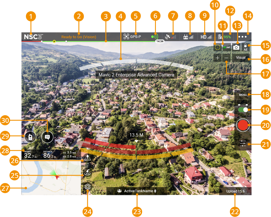
- 1Back - Tap this icon to return to the main menu.
- 2System Status - This icon indicates aircraft flight status and various warning messages.
- 3Battery Level Indicator - The battery level indicator provides a dynamic display of the battery level. The colored zones on the battery level indicator represent the power levels needed to carry out different functions. The first dot on the left is when the aircraft will try to automatically land in its current location due to low power. The yellow H indicates when the app will try to activate Return-to-Home (RTH) unless you stop it. The yellow H represents your home point and moves along the line to show how much power you will need to get your drone back home. On the right side of the indicator, you can see the estimated remaining flight time.
- 4Obstacle Detection Status (appears also in iOS if objects are close by) - Bars are displayed when there are obstacles close to the aircraft. The bar color changes between green, orange, and red depending on how close the detected obstacle is. The distance to a detected obstacle is also shown in meters.
- 5Flight Mode - The text next to this icon indicates the current flight mode.
Positioning mode (P-mode) works best when the GPS signal is strong. The aircraft utilizes the GPS and Vision Systems to locate itself, automatically stabilize, and navigate between obstacles.
Sport mode (S-mode) the flying speed restrictions are lifted and the aircraft will not be able to sense and avoid obstacles. Aircraft responses are optimized for agility and speed making them more responsive to stick movements.
In Tripod Mode the maximum flight speed is limited to 3.6 kph (2.2 mph). Responsiveness to stick movements is also reduced for smoother more controlled movements.
The aircraft will revert to Altitude/ATTI mode (A-mode) when the GPS signal is weak, or when the compass experiences interference where the Vision System is unavailable. In ATTI mode the aircraft is easily affected by its surroundings, which may result in horizontal shifting. Please land in a safe place as soon as possible to avoid hazards.
In OPTI mode the aircraft is only using its vision system to stabilize its position.
When activating Return-to-Home (RTH), the flight mode changes to GoHome.
When Return-to-Home (RTH) is activated, and the aircraft has reached the Home location, the flight mode changes to Landing as the aircraft starts to descend.
- 6Vision System Status - This shows the current status of the various proximity sensors on the aircraft. Green means the corresponding sensor is active, and red means the sensor is inactive.
- 7GPS Signal - Shows the current GPS signal strength. White bars indicate adequate GPS strength, red bars indicate low GPS strength. Avoid flying in areas where the GPS signal is weak. The aircraft will otherwise be forced to enter ATTI mode, leading to a potential flight hazard.
- 8Remote Controller Signal - This icon shows the strength of the remote controller signal. Interference in the signal will be displayed as a warning in the system status. When there are no additional warnings, it means that the interference will not affect the operation and overall flight experience.
- 9HD Video Link Signal Strength - This icon shows the strength of the HD video downlink connection between the aircraft and the remote controller. Interference in the connection will be displayed as a warning in the system status. When there are no additional warnings, it means that the interference will not affect the operation and overall flight experience.
- 10Focus/Metering Mode Button - Tap to switch between focus and metering mode. Tap to select an object for focusing or metering. Auto Focus-Continuous will be triggered automatically according to the status of the aircraft and camera after enabling.
- 11Auto Focus - Auto/Manual Focus Button - Tap to switch between Auto Focus and Manual Focus.
- 12Battery Level - This icon shows the current battery level of the aircraft.
- 13Camera Parameters - Tap the camera icon to reveal/hide the camera settings parameters, media type, and capacity of the Micro SD card.
- 14General Settings - Tap to enter the general settings menu for setting server connection, user login, and so on.
- 15Auto Exposure Lock - Tap to lock the exposure value.
- 16Switch between camera image layers (Visual/Thermal/Split). These may vary based on your drone model.
- 17Camera Zoom - Tap to zoom in and out with the camera.
- 18Camera Menu - Tap to enter general camera settings for settings such as photo mode, capture resolution and format, and so on.
- 19Photo/Video Button - Tap to switch between photo and video recording modes.
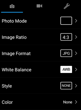
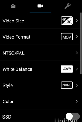
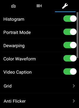
- 20Shoot/Record Button - Tap to start shooting photos or recording video.
- 21Camera Settings - Tap to enter the camera parameter settings.
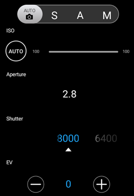
- 22Upload Status - Shows the current data transfer speed to the server.
- 23Active task that you are currently broadcasting to
- 24Flight Settings - Tap to edit the maximum flying and Return-to-Home (RTH) altitudes.
- 25Smart RTH - Initiate Return-to-Home (RTH) home procedure. Tap to have the aircraft return to the last recorded home point.
- 26Auto Takeoff/Landing - Tap to initiate auto takeoff or landing
- 27Map - Tap to open the Map view.
- 28Flight Telemetry - Height from the Home Point - Distance between the aircraft and the Home Point - Aircraft vertical speed - Aircraft horizontal speed.
- 29Push-to-talk – communicate with the task members through a voice channel.
- 30Send quick reactions or chat messages to your team members
5. Map view
Android
iOS
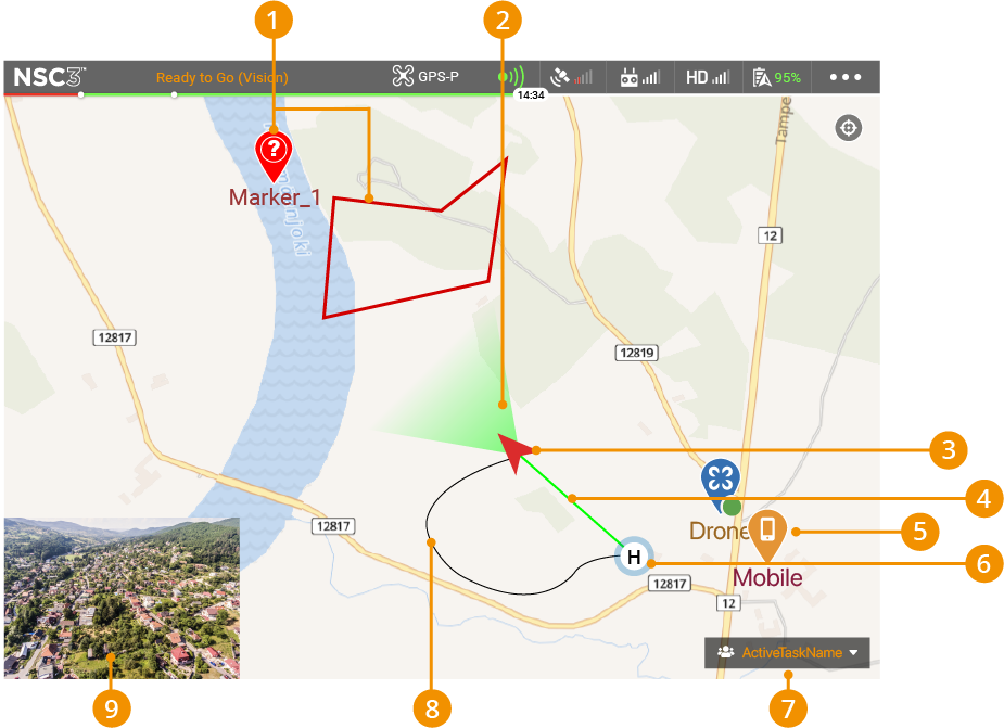
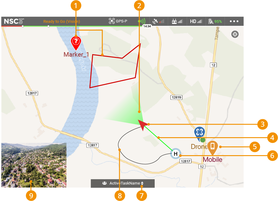
- 1Map Markers - A point of interest or an area created by the operation control to highlight specific locations on the map.
- 2Camera View Direction - Shows the orientation of the aircraft camera.
- 3Aircraft Location - Shows the location of the aircraft.
- 4Direct Path to Home Point - Shows a direct path from the aircraft to the Home Point.
- 5Other Device locations.
- 6Home Point (outside the view in iOS-view) - Home Point for the aircraft to return to. It can be the takeoff location or a user chosen location.
- 7Group Selection - Opens a list of groups the device has been assigned to. Only devices and map markers from the selected group are visible on the map.
- 8Flight Path History - Shows the recorded flight path from the Home Point to the current location.
- 9Camera View - Tap to go back to the Camera view.
6. Widgets
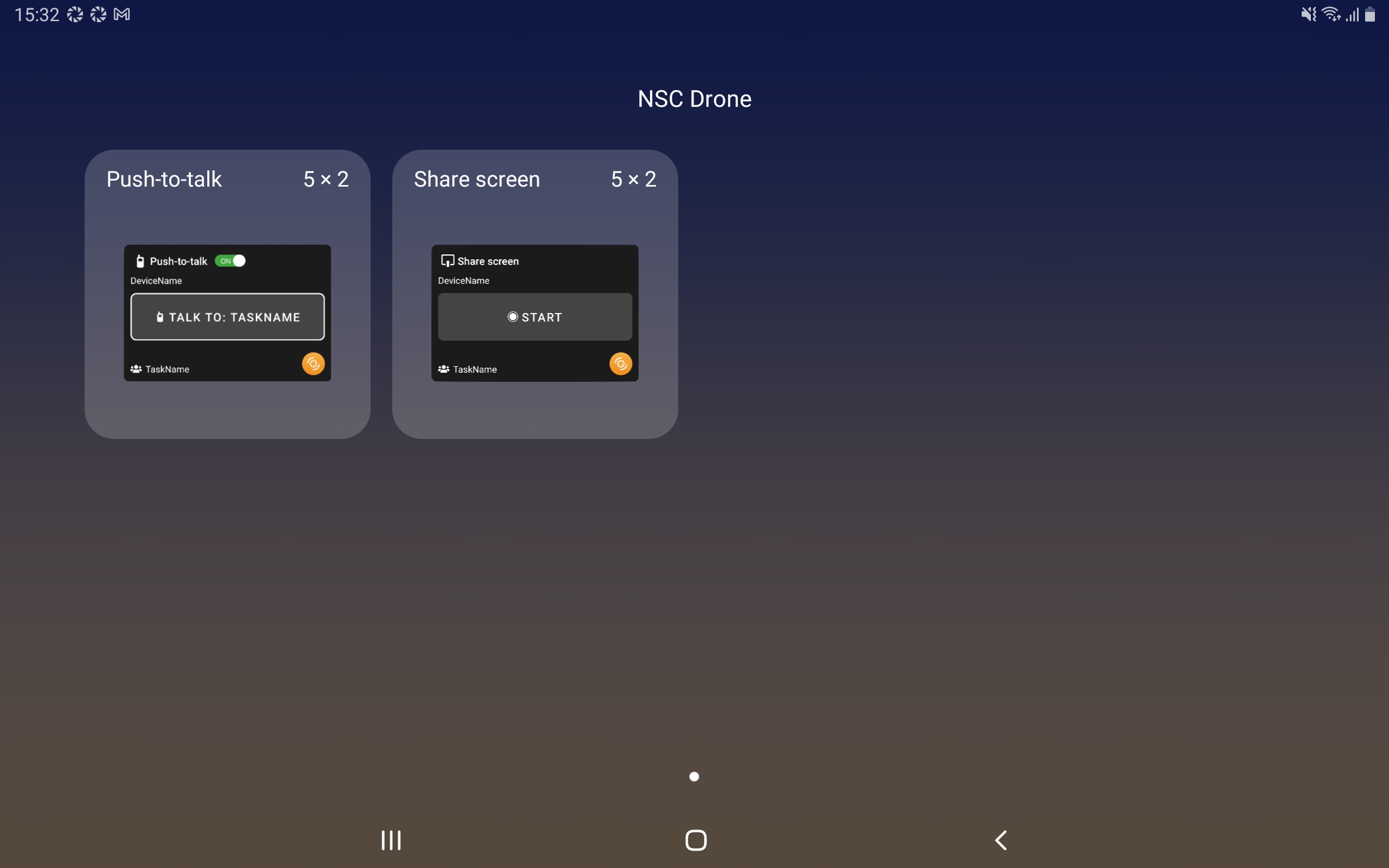
Widgets are currently available only for Android devices. Push-to-talk and screen share features are available as Android widgets. To find them, navigate to your smart device’s widgets.
More information on Android widgets can be found on https://support.google.com/android/answer/9450271?hl=en
